
The word television literally means "vision at a distance." We like to think of a television screen as a "window" through which a televiewer can watch a scene that may be taking place many miles away. Let us face the fact that television engineers and broadcasters are in the business of creating illusions. What we actually create on the kinescope in a televiewer's home is a constantly changing pattern of light generated by a tiny flying spot, but we can make this pattern of light stimulate the eye and nervous system of the televiewer in such a way that he gets the illusion of actually witnessing a scene taking place before the television camera. Naturally, we would like to make this illusion as convincing as possible so as to put a minimum strain on the televiewer's imagination.
Color television is more appealing than black-and-white television mainly because it is capable of producing more convincing illusions. Normal vision for the vast majority of human beings is color vision, so any picture-producing process that does not include color puts more of a strain on the observer's imagination than does one that includes color. Fortunately, the eve and the brain are sometimes easy to satisfy in these respects. We have built tip a very impressive television industry by producing pictures in black-and-white only. While images show green grass, blue skies all in the same monotonous shade of gray usually succeed in giving the desired perceptions, they would be much more effective if presented in full color. In fact, there are many types of subjects (notably outdoor scenic views) which are very uninteresting in black-and-white but which have real aesthetic value when presented in color.
When we study the problem of developing a color television system suitable for a broadcasting service, we quickly discover that we cannot confine our attention to technical factors alone. To determine the suitability of any particular color television system we must consider not only the technical requirements (Does it produce high quality pictures?) but also the factors of Government regulations (Does it satisfy FCC requirements?), economics (Does it permit mass produced receivers, and does it permit the broadcaster to initiate a color broadcasting service without great financial risk?), public interest (Does it in any way detract from the value of an existing broadcast service?), and conservation of resources (Does it make the most effective possible use of the frequency spectrum?).
After examining all of the pertinent factors, we may establish a list of minimum requirements for a broadcast color television system. The writer feels that the following list is supported by the vast majority of engineers in the industry.
In 1949, the Radio Corporation of America announced the development of a color television system which it felt provided a satisfactory framework for a broadcast service. Since 1950, RCA engineers have collaborated with the engineers of many other companies through the medium of the National Television System Committee to work out a set of signal specifications which result in optimum performance within the broad framework of the original RCA system. These signal specifications, in final form, were submitted to the FCC for approval on July 23, 1953 and they were approved on December 17, 1953. This paper describes the principles of operation of the RCA color system, and presents explanations for the exact signal specifications approved by the FCC, under which the system meets the basic requirements listed earlier.
Color vision for the great majority of human beings has three more or less independent attributes-these are: brightness, hue and saturation. Brightness is most clearly explained to television engineers by stating that it is the only characteristic of colors that is transmitted by an ordinary black-and-white television system; brightness is that characteristic by means of which colors may be located in a scale ranging from black (darkness) to maximum white. Hue is that characteristic by means of which colors may be placed in categories such as red, green, yellow, blue, etc. Saturation refers to the degree by which a color departs from a gray or neutral of the same brightness; pale or pastel colors are much less saturated than those that are "deep" or vivid.
It should be apparent at this point that one of the problems involved in converting a monochrome television system to a color television system is the problem of handling additional information. Instead of controlling the single variable, brightness, we must control three independent variables, brightness, hue, and saturation. To do this, we must provide no fewer than three independent signals, and they must be of such a nature that they can be produced by physically-realizable pick-up tubes and utilized by physically-realizable reproducing devices. To show bow these colorimetric requirements can be met by a practical color television system, let us consider briefly the relationships between color sensations and the light energy that constitutes the physical stimulus.
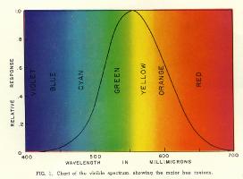 It is a matter of common knowledge that there is a strong similarity between light and radio waves. We designate as light those electromagnetic waves to which the human eye is sensitive, extending over wavelength range of roughly 400 to 700 millimicrons (a millimicron is one-billionth of a meter). The response of the eye is not uniform over this region, but follows a response curve shaped very much like a probability function and peaked at 555 millimicrons, as shown in Fig. 1. This curve describes the spectral characteristics of the brightness sensation only, and indicates that a given amount of energy may appear much brighter at some wavelengths than at others. Response curves vary somewhat from person to person, but Fig. 1 shows the specific curve representing the average response of a great many observers and adopted by the International Commission on Illumination in 1931 as the standard luminosity function or visibility curve.
The other two variables of color-hue and saturation-are controlled by the relative spectral distribution of light energy. To a first degree of approximation, hue is determined by dominant wavelength. In fact, the various wavelength regions of the visible spectrum are commonly designated by specific hue names, ranging from violet and blue for the very shortest wavelengths through cyan (or blue-green), green, yellow, and orange to red for the longest wavelengths. These major hue regions are designated roughly on Fig. 1. Saturation is determined by radiant purity, or the extent to which the light energy is confined to a single wavelength or a very narrow band of wavelengths.
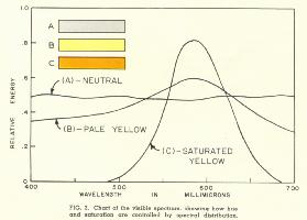 Fig. 2 should serve to illustrate how hue and saturation are controlled by the spectral distribution of light energy. If the radiant energy from a color is spread out more or less uniformly over the visible spectrum, as shown at A, it is generally perceived as white (or gray, depending upon the relative brightness). If the distribution curve has a slight hump or peak, the color is perceived as a pale or pastel shade of the hue corresponding approximately to the dominant wavelength. For example, a color with a distribution curve corresponding to curve B would be perceived as a pale yellow. If the distribution curve consists of a fairly sharp peak around the same dominant wavelength, as shown in curve C, the color generally has the same hue but is more highly saturated. Maximum saturation occurs when the spectral distribution curve is a single line, corresponding to single-wavelength radiation.
Psychologists and physiologists are still searching for a completely satisfactory explanation as to how human beings are able to perceive colors. The most promising theory of color vision is based on the assumption that there must be three kinds of cone cells in the human retina with over-lapping spectral sensitivity curves but with peaks occurring in roughly the red, green and blue portions of the spectrum. According to this theory, the brightness sensation is controlled by the sum of the responses of the three types of cells, while hue and saturation are determined by the ratios of stimulation. Fortunately, we do not need a complete understanding of all the intricate processes involved in human vision in order to develop a color-reproducing process, because we may employ the primary color concept, which has been verified (though not completely explained) by a great body of experimental data.
It is an experimentally proved characteristic of human vision that nearly all of the colors encountered in everyday life can be matched by mixtures of no more than three primary colors. Consequently, it is possible to produce full-color images of complete scenes by superimposing three primary color images; this basic process is used by nearly all modern color-reproducing systems, including color photographs and color television. Contrary to popular belief, there is no one set of colors with "sacred" properties that make them the primary colors-any set of three will do, provided only that no combination of any two is capable of matching the third. It so happens that the most useful set for color television purposes (i.e., the set with which it is possible to match the greatest range of everyday colors) consists of highly-saturated red, green, and blue. The FCC signal specifications use standard colorimetric designations to describe the specific set of red, green and blue primaries recommended for color television.
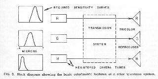 The calorimetric principles used in color television are illustrated by Fig. 3. At the receiving end of the system, a full-color image is produced by adding the light output of three registered images in red, green and blue. There are three basic methods for combining the primary images: (a) Superposition by means of dichroic mirrors or by projection to a common viewing screen, (b) rapid sequential presentation at a rate fast enough to cause addition by the "persistence of vision" effect, or (c) presentation of the images in the form of intermingled primary color dots or other elements too small to be resolved separately.
Since the final color picture involves three variables, the color camera must provide three independent video signals. To accomplish this, the camera must have, in effect, three independent pick-up or transducing elements. In some color cameras, three entirely separate pick-up tubes are used in conjunction with an image-dividing optical system, but it is also possible to combine the three sets of transducing elements in a single tube envelope or to use a single tube in three different modes of operation (by means of rotating optical filters). The simplest type of color camera from an analytical point of view is one in which three pick-up tubes are used to provide red, green, and blue signals directly, as indicated in Fig. 3. By calorimetric techniques which are too complex to be explained here, it is possible to compute precisely the optimum shapes for the spectral sensitivity curves of the three pick-up tubes to yield the best color fidelity for the average observer. The sketches in Fig. 3 give a rough indication of the optimum spectral response curves (but readers familiar with colorimetry will note that the secondary response lobes have been eliminated). Note that the peaks of the curves occur in roughly the red, green, and blue portions of the spectrum, but that they overlap appreciably. The relative sensitivities of the three camera tubes are usually adjusted so that the output voltages are equal when a white or neutral is being scanned. In analyzing and discussing television systems, it is customary to express signal voltages in relative or percentage units, such that 100% voltage in all three channels corresponds to the brightest white the system can reproduce.
All systems of color television are based on the same calorimetric principles, regardless of the physical construction of the cameras and receivers or the methods used to combine the primary color images. In principle, the various systems differ only solutions they offer for the multiplexing problem involved in transmitting the signals from camera to receiver. The simplified block diagram in Fig. 3 shows green and blue signals entering the transmission system. It should be appreciated that these signals may be operated upon in a great variety of ways within the transmission system; the only requirement is that they must remain sufficiently independent that red, green and blue signals suitable for the control of a tricolor reproducer can be recovered at the receiving end. A complete discussion of all proposed multiplexing methods for color television is beyond the scope of this paper, so we shall confine our attention to the techniques currently used in the RCA color television system under the FCC signal specifications.
In keeping with the principle that education is best accomplished by leading the student from the known to the unknown in gradual, easy-to-follow steps, the writer shall attempt to explain the RCA color television system by showing how a black-and-white television system can be transformed, step-by-step into a compatible color system. The reader should keep in mind that our ultimate goal is to develop a color television system meeting the colorimetric requirements shown in Fig. 3 as well as the other requirements listed in the introduction to this paper. While particular attention will be directed here to the difference between black-and-white and color systems, the reader should appreciate that there are fundamental similarities. For example, the methods of scanning and of maintaining synchronism between the camera and the receiver are the same for both black-and-white and color television systems.
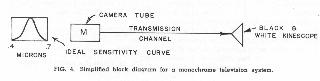
A black-and-white television system reduced to the simplest possible terms is shown in Fig. 4. The system consists, in essence, of a black-and-white kinescope connected to a camera tube through a transmission channel. It must be understood, of course, that means are provided for scanning the image areas of both the kinescope and the camera tube in synchronism, and that other means are provided for transmitting an audio signal from the camera location to the receiver. For optimum performance the camera tube should have a spectral sensitivity curve matching that of the eye (the luminosity function) so that the various colors in an original scene are reproduced in appropriate tones of gray corresponding to their relative brightnesses. The monochrome signal from such a camera tube, which we shall designate as M throughout the rest of this paper, may be regarded as a luminance signal. ( see footnote /1)
If the signal produced by a color television system is to provide service to black-and-white receivers, we should devise some method of producing a luminance signal from the output of the color camera. We might attempt to use the signal obtained from just one of the three camera tubes, but we would quickly discover that this technique is unsatisfactory because certain colors would be rendered on black-and-white receivers in inappropriate tones of gray. For example, if we were to use the signal from the green camera tube to control black-and-white receivers, we would find that both red lips and blue skies would be too dark in the black-and-white images, because the green pick-up tube has very little response for either red or blue light. We can, however, produce a very reasonable luminance signal by adding the signals from the red green, and blue camera tubes in proportion to the relative luminosities of the primaries.
The three primaries recommended as standards for color television do not appear equally bright because they are located in different parts of the spectrum, and hence stimulate the brightness sensation by different amounts. If the three primaries are mixed together in the right proportions to produce a white matching typical daylight, it is found that the green primary (located at the center of the visible spectrum) accounts for 59% of the brightness sensation, while the red and blue primaries account for only 30% and 11%, respectively.
If the red, green, and blue spectral sensitivity curves shown (in very rough form) in Fig. 3 are added, wavelength by wavelength, in the ratio of 30% red, 59% green, and 11% blue, the resulting curve has the same shape as the luminosity function, which is the optimum curve for a black-and-white camera, as shown in Fig. 4. We can accomplish this addition electrically by combining the signals from the red, green, and blue camera tubes in a simple resistance mixer, as shown in Fig. 5, to produce a monochrome or M signal equal to .30R + .59G + .11B. (The three weighing factors have been adjusted so that their sum is unity. Consequently, when a peak white is being scanned, and R = G = B = 100 the M signal also equals 100%.) If three camera channels were linear-that is, if the signal voltages were strictly proportional to the light inputs-the M signal would be identical to that produced by a linear black-and-white camera with optimum spectral response. In actual practice, the camera signals are deliberately made non-linear to compensate for the nonlinearity of the kinescopes used in receivers, but the M signal is still a good approximation to the output of a black-and-white camera.
From the preceding discussion, we may draw the conclusion that it is possible to make a color television system compatible in the sense of providing service to black-and-white receivers by cross-mixing the and blue primary signals to produce a monochrome signal according to the equation M = .30R + .59G + .11B. This signal should be generated in accordance with the existing scanning standards (i.e. 525 lines, 60 fields/second, 30 frame second), and be treated exactly like standard monochrome signal with respect to bandwidth and the addition of synchronizing and blanking pulses. 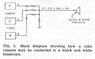 If we were to stop our development at this point, we would not yet have a color television system; so far we have developed only a reasonable method for connecting a color camera to a black-and-white receiver, as shown in Fig. 5. In order to produce color pictures, we must provide at least two other independent signals in addition to the M signal, since color involves three independent variables. If we are to continue to satisfy the requirement of compatibility, we must find means for transmitting these additional signals through a standard broadcast channel without interfering with the monochrome signal.
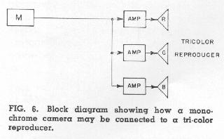 The choice of signals to accompany the M or monochrome signal in a compatible color system can best be determined by considering the requirements of a color receiver. One requirement a color system should satisfy is what is often called "reverse compatibility"; that is, the color receiver should be capable of producing a black-and-white picture from a standard monochrome signal. This requirement is readily satisfied by arranging the receiver at a monochrome signal may be applied to all three kinescope elements in equal proportions, as shown in Fig. 6. Whenever the red, green, and blue elements of a tricolor reproducer are excited in a one-to-one-to-one ratio, a white or neutral is reproduced. (Note: This 1: 1: 1 ratio applies only to normalized voltages such that 100% voltage on all three kinescope elements - produces a maximum white. The absolute drive voltages may be different because of the different efficiencies of the various phosphors.)
The additional signals required to produce a color picture are indicated in Fig. 7. From an inspection of the figure, it should be obvious that we can provide the R, G, 11 signals required for the color kinescope if we have R-M, G-M and B-M signals which may each be added to M in the simple arrangement shown. R-M, G-M, and B-Al are called chrominance or color-difference signals; when considered in combination, they indicate how each color in the televised scene differs from a monochrome color of the same luminance. 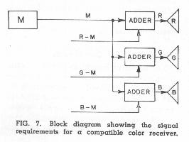 We still retain the feature of reverse compatibility, because when the receiver is tuned to a transmission where the R-M, G-M, and B-M signals are absent, the monochrome signal is still applied to the kinescope elements in equal proportions, thus prod ing a black-and-white picture. (An adder usually consists of a pair of amplifier stages with separate grids but a common plate load impedance.)
A superficial study of Fig. 7 would seem to indicate that a total of four signals are required for our compatible system. Since color has only three variables, it seems reasonable that it should be possible to achieve the desired results with only three independent signals. A study of the R-M, G-M and B-M chrominance signals shows that they are not independent-when any two of them are known, it is always possible to solve for the third. This fact may be proved by first writing the signals in terms of their red, green, and blue components and then testing the resulting equations by any of the standard tests for independence to see if they constitute a set of three independent, simultaneous equations. It was noted earlier that M = .30R + .59G + 11B.
Therefore:
These equations cannot be solved for R G, and B in terms of R-M, G-M, and B-M, but they can be solved to find any of the chrominance signals in terms of the other two. For example,
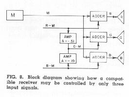 In the arrangement shown in Fig. 8, equation is solved automatically and continuously by a simple cross-mixing circuit that combines appropriate amounts of R-M and B-M signals. The separate amplifier stages in the mixer inherently provide the polarity reversals implied by the minus signs in the equation. The arrangement shown in Fig. 8 is fully equivalent to that shown in Fig. 7, but the receiver requires only three input signals instead of four. It should be noted that G-M might have been chosen as one of the two chrominance signals to be transmitted, but R-M and B-M are the two that were actually selected for use in the system.
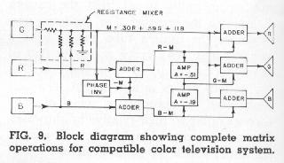 Let us now direct our attention toward the transmitting end of the system to see how the chrominance signals may be obtained from a color camera. We have already shown (in Fig. 5) how a luminance or monochrome signal may be obtained by cross-mixing the R, G, B signals in a simple resistance mixer. Fig. 9 shows how a phase inverter and a couple of adders may be employed to provide all the signals needed to produce a color picture. Our problem now is to find means for transmitting the R-M and B-M signals from the camera to the receiver without causing interference to the M signal.
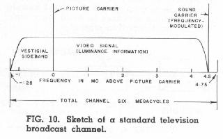
Fig. 10 shows how a six-megacycle broadcast channel is utilized by a standard monochrome picture signal and the associated frequency-modulated sound signal. This is the same channel that must be used for all the information required for our compatible color television system. Since we have already noted that the M component of our color signal should be treated in all respects like an ordinary monochrome signal, it seems, at first glance, that this one component alone will completely fill the available channel, leaving no spectrum space for the additional chrominance signals. It has been found, however, that an additional carrier may be transmitted within the same spectrum space occupied by the luminance signal without causing objectionable interference, provided the added carrier is separated from the main picture carried by some odd multiple of one-half the line frequency. This added carrier may be modulated by a video signal, and thus made to convey additional information. This multiplexing technique is commonly known as frequency interlace.
In practice, the use of an additional transmitter for a color television system is avoided by using the subcarrier principle. That is, the extra information to be transmitted on the added carrier is first modulated upon a subcarrier of less than 4 MC somewhere within the studio, and this modulated subcarrier is then added directly to the monochrome signal. Thus all the color signals are combined into one signal before leaving the color studio, so only one transmission line and one transmitter are required. The subcarrier frequency is chosen as an odd multiple of one-half the line frequency, and this frequency spacing between the subcarrier and the main picture carrier is preserved when the combined signals are modulated upon the picture carrier within the transmitter.
Basically, the frequency-interlace technique is a means for exploiting the "persistence of vision" effect to permit the transmission of additional information. Persistence of vision, or the time-integrating property of the human eye, is relied upon even in monochrome television systems; it provides the illusions of smooth motion and continuous illumination from the rapid succession of still images that is actually transmitted. Fortunately for the color television system designer, visual stimuli are integrated or averaged by the eye over considerably longer periods of time for small picture areas than for larger picture areas. Consequently, interfering signals which appear only as small-area dots in the picture may be cancelled out by the eye if provision is made for reversing the polarity of the "dots" between successive scans of each area in the picture.
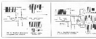
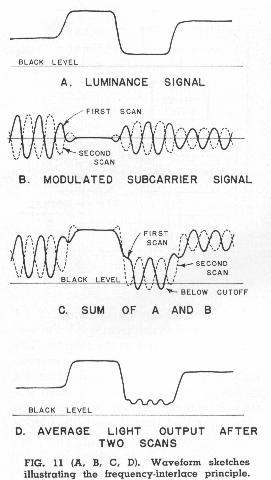 The clearest way to explain how frequency interlace works is by means of waveform sketches, such as those in Fig. 11. Sketch (A) shows a typical luminance signal for a very small section of one scanning line. Sketch (B) shows the modulated subcarrier signal to be transmitted during the same interval. If the subcarrier is an odd harmonic of one-half the line frequency, it reverses in polarity between successive scans (as indicated by the dotted line) because it passes through some whole number of cycles plus one-half during each frame period. The composite signal to be transmitted-the sum of (A) and (B) is shown at (C). We shall discuss in a later section how chrominance information may be modulated on the subcarrier and later removed from it by demodulation, but at this point we should note that the signal shown at (C) is the one that would be applied to black-and-white kinescopes when ordinary monochrome receivers are tun to a compatible color transmission. The signal that should ideally be applied to kinescopes is the luminance signal shown at (A); the subcarrier component is spurious whenever it reaches a kinescope instead of a demodulator. Nevertheless, the interference caused by the subcarrier is not objectionable, because it is effectively cancelled out by the persistence of vision. The effective response of the eye is controlled not so much by the instantaneous stimulation provided by any one scan as by the average stimulation after two or more scans. The average signal after two scans is shown at (D). Note that this is identical to the original luminance signal except in cases where the composite signal overshoots below black level; the kinescope is incapable of producing negative light to cancel the positive peaks.
In the interests of accuracy, it should be noted that cancellation of spurious signals by the frequency interlace technique is seldom 100% complete, for the following reasons: (1) For perfect cancellation, the sinusoidal electrical signals shown in Fig. 11 should be transformed to sinusoidal light patterns before reaching the eye; in practice, the electrical signals are applied to non-linear kinescopes which effectively alter the waveforms to make perfect cancellation impossible (the overshoots below black level are an exaggerated case of this general effect). (2) The persistence of vision effect is not perfect over an interval of 1/15th of a second (two frame periods). (3) When there is motion in the image, the waveforms change slightly from frame to frame. On the other hand, the lack of perfect cancellation is not objectionable in practice because: (1) Many mass produced receivers have relatively low response at the subcarrier frequency specified by FCC Standards (roughly 3.6 MC), so the subcarrier component is pretty well attenuated before it reaches the kinescope. (2) The signals modulated on the subcarrier have the same image geometry as the luminance signal, so any crosstalk resulting from imperfect cancellation does not confuse the picture but simply adds dots or alters gray-scale values in certain areas. (3) The dot pattern resulting from imperfect cancellation corresponds to the second harmonic of the subcarrier, and is therefore even finer in texture than the line structure and cannot be resolved at normal viewing distances.
The reader may wonder at this point y transmit not one but two signals (both R-M and B-M) by the frequency-interlace technique. It is not desirable to use two separate frequency-interlaced carriers, because the difference frequency between them would be an even multiple of one-half the frame frequency, and hence would have no tendency to be self-cancelling. The difference frequency would be produced as a "beat" between the two carriers whenever the signal is passed through any non-linear device, such as a kinescope. The need for two carrier frequencies can be eliminated by the use of the two-phase modulation technique, which is equivalent to the use of two carriers of the same frequency but with a phase separation of 90 degrees.
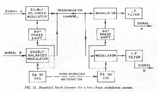
The basic equipment needed for a two-phase modulation system is shown in Fig. 12. For purposes of illustration, let us assume that the carrier frequency is approximately 3.6 MC; we shall discuss the factors involved in choosing a precise subcarrier frequency in a later section. In the arrangement shown, two independent signals are modulated upon two carriers of the same frequency but 90 degrees apart in phase. The outputs of the two transmitter modulators are added together to feed a common transmission channel. The two independent components are separated at the receiving end by means of two additional modulators (operated as synchronous detectors) which multiply the incoming signal by two carriers having the same relative phases as original carriers at the transmitter. The carriers at the receiver must be supplied by an oscillator which is maintained in frequency and phase synchronism with the master oscillator at the transmitter; some form of special synchronizing information must be transmitted for this purpose.
The two-phase modulation technique is basically a means for using the two sidebands surrounding a single carrier frequency for the transmission of two variables. It is common knowledge among radio engineers that double-sideband transmission is ordinarily wasteful of spectrum space, since the information contained in the two sidebands is identical. Whereas an ordinary AM wave varies in one respect only (i.e., in amplitude), the signal transmitted by, a two-phase modulation system varies in both amplitude and phase.
The most serious disadvantage of the two-phase modulation technique is the need for carrier reinsertion at the receiver. This characteristic makes the technique economically undesirable in many applications, but its use in compatible color television systems is entirely feasible because of the happy fact that time is available (during the blanking intervals necessarily provided in a television system) for the transmission of carrier-synchronizing information. Under the FCC Color Signal Specifications, the subcarrier-synchronizing information consists of "bursts" of at least 8 cycles of the subcarrier frequency at a predetermined phase transmitted during the "back porch" interval following each horizontal synchronizing pulse, as shown in Fig. 13.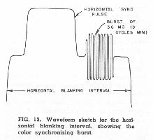 The "bursts" are separated from the rest of the signal at the receiver by appropriate time-gating circuits, and are used to control the receiver oscillator through a phase detector and reactance tube.
The need for carrier reinsertion in a compatible color television receiver need not be regarded as a serious disadvantage when account is taken of the fact that an important advantage - suppressed carrier transmission-may be gained without further complexity. In ordinary AM broadcasting, fully half of the radiated energy is in the carrier component, which transmits no information by itself but simply provides the frequency reference against which the sidebands may be heterodyned in simple diode detectors to recover the intelligence in the sidebands. If a locally generated carrier is available in the receiver, then there is no need to transmit a carrier along with the sidebands. In a compatible color television system, suppression of the subcarrier not only saves signal energy but also reduces the possibility of spurious effect in images, since the complete subcarrier component goes to zero (and hence can not cause interference whenever the camera scans a white or neutral surface such that both R-M and B-M equal zero.
A brief review od some of the characteristics of amplitude modulators may be appreciated at this point before we undertake further discussion of suppressed-carrier transmission and two-phase modulation. Let us confine our attention here to the one type of modulator most commonly used in color television at the present time-the suppressor-grid type. The basic circuit is shown in Fig. 14, and its operation may be described rather crudely as follows: The number of electrons leaving the cathode of the tube is roughly proportional to the signal voltage on the first grid (assuming reasonable linearity), since the screen grid prevents the third grid and the plate from exercising any significant influence on the space current. The proportion of the emitted electrons that reach the plate instead of the screen is roughly proportional to the relative voltage on the No. 3 grid. If the No. 3 grid is positive, the screen grid collects only a few of the electrons, and most of them are attracted to the plate, which is of higher potential. If the No. 3 grid is highly negative, however, it may make a potential barrier so great that no electrons can pass through to the plate and all of them are collected by the screen. Therefore, the plate current contains a component proportional to the product of the signal on the No. I grid and that on the No. 3 grid. The suppressor-grid modulator, like most simple modulators, produce an output consisting of three components as indicated in Fig. 14. In addition to the product component, both the original video signal and the carrier signal appear (with polarity reversals) as if the tube were a simple amplifier as well as a modulator. The relative amplitudes of the three components depend upon the tube type, the relative input levels, and the bias conditions.
In many modulator applications, the original intelligence signal (video or audio, as the case may be) is removed at the output by filtering. For example, in AM sound broadcasting, the output of the modulator is usually a tuned circuit which offers almost no impedance to the original audio frequencies. Removal of the carrier component by filtering is very difficult in most practical circuits, since it is difficult to make a filter "sharp" enough to attenuate the carrier without also affecting the sidebands. As an alternative to filtering, the method of cancellation may be used to remove the original intelligence signal, the carrier, or both original components from the output of a modulator. A typical doubly-balanced modulator, which uses the method of cancellation, is shown in simplified form in Fig. 15. The circuit consists essentially of two modulator tubes with opposite-polarity inputs and a common output. The input components cancel each other in the common output, but the product components reinforce each other. Therefore, the output consists only of pair of sidebands with no carrier. A cent tapped transformer may be used as a phase splitter for the carrier signal, but a tube type phase splitter is required for the intelligence signal if it involves frequency components of more than a few KC. It should be noted that if such a modulator circuit is to be used for television signals with significant DC components, clamps or DC restorers must be used at each modulator grid. Circuits of this basic type have been widely used in experimental color television studio equipment.
One significant difference between an ordinary AM wave and a suppressed-carrier signal is that the latter goes through a polarity reversal every time the intelligence signal passes through zero. For this reason, an ordinary diode or envelope detector cannot be used to demodulate a suppressed carrier signal. As long as both sidebands are transmitted, however, the suppressed carrier signal remains of constant phase even though it may swing both positive and negative. The intelligence signal may be recovered by the process of synchronous detection.
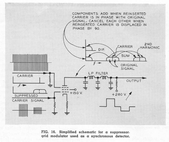
The operation of a suppressor-grid modulator as a synchronous detector is illustrated by Fig. 16. Detection, like modulation, is essentially a heterodyning process whereby signals may be moved to new positions in the frequency spectrum. In a modulator, an intelligence signal is heterodyned against a carrier, and the sum and difference frequencies appear as a pair of sidebands surrounding the carrier. In a detector, the pair of sidebands is heterodyned against a carrier (whether that carrier was transmitted along with the sidebands or reinserted at the receiver), and again sum and difference frequencies are produced. The sum frequencies consist of a pair of sidebands surrounding the second harmonic of the carrier, and ordinarily are of no value. The difference frequencies, however, represent the original intelligence. As noted in Fig. 16, the difference frequencies from the two sidebands reinforce each other if the carrier at the detector is in phase with the original carrier, but they cancel each other if the carrier at the detector is 90 degrees out of phase with the original carrier. This last-mentioned characteristic of synchronous detectors is the basic principle on which the two-phase modulation technique rests. If the input to a synchronous detector consists of the sum of two suppressed-carrier signals in phase quadrature, the phase of the carrier applied to the detector may be adjusted to cause the difference frequencies representing one of the two components to add while the difference frequencies representing the other signal will cancel out. Obviously, a second detector can be used with a carrier displaced by 90 degrees to recover the signal that is cancelled in the first detector.
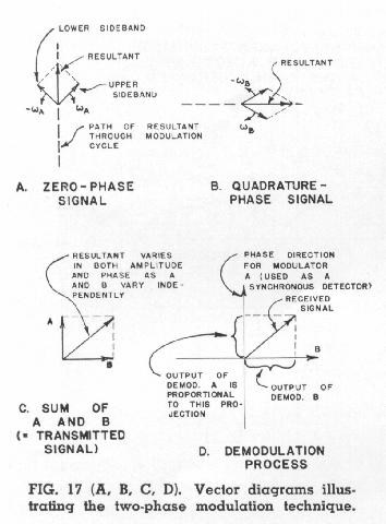 A vectorial representation of the two phase modulation technique is shown in Fig. 17. It is conventional to portray the two sidebands of an amplitude-modulated wave as vectors which revolve with same angular velocity but in opposite rections relative to the carrier. The car is suppressed in Fig. 17 but each sketch must be regarded as revolving about its origin at the carrier frequency. The sketch at (A) shows the two sidebands produced by suppressed-carrier modulation of a carrier of reference phase. Note that the resultant always fall somewhere on the vertical line, since the quadrature components of the sidebands cancel each other at all times. A different signal, B, modulated in suppressed-carrier fashion upon a second carrier in phase quadrature produces the pair of sidebands shown in sketch (B). The resultant in this case is also of constant phase. The sum of both resultants is shown in sketch (C). Since A and B vary independently, the transmitted signal may have any phase angle at any given instant. As shown in sketch (D), the original signals may be recovered by synchronous detectors each of which is sensitive only to the projection of the vector for the transmitted signal into the phase reference direction corresponding to the phase of the reinserted carrier. Since the projection of the B component into the A direction is zero, and the projection of the A component into the B direction is also zero, the two original signals may be recovered without crosstalk as long as both sidebands are transmitted.
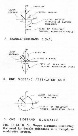 The need for double sidebands in a two phase modulation system is illustrated by Fig. 18, which shows the vectors corresponding to amplitude modulation of a single suppressed carrier. As long as both sidebands are transmitted with equal levels, the phase of the resultant remains constant, as shown in sketch (A), and the projection of the resultant into the plus or minus 90 degree phase direction remains at zero (indicating a lack of crosstalk). Sketch (B) shows what happens when the sidebands become unequal. The path of the resultant through the modulation cycle is now an ellipse, rather than a straight line, and the projection of this ellipse into the plus or minus 90 degree phase direction represents crosstalk. If one sideband is completely missing, the path of the resultant becomes a circle as shown in sketch (C), and the amplitude of the crosstalk component becomes equal to the desired component. While it is possible to devise means for cancelling this crosstalk (by making use of the fact that there is a 90' phase separation between the desired and crosstalk components), it is better to avoid it entirely by providing double sidebands for two-phase modulated signals.
It should now be quite apparent that we the requirements for a compatible color television system by cross mixing (or matrixing) the R, G, B primary signals to produce M, R-M, and B-M signals, by treating the M signal like an ordinary monochrome signal, by modulating R-M and B-M in phase quadrature upon a frequency-interlaced subcarrier, and by adding this modulated subcarrier to the M signal for transmission. Before we can complete the system development, however, we must decide at what relative levels the various signal components are to be transmitted, and what bandwidths should be allotted to the various signal components. The factors involved in the former decision can be determined by a study of the waveforms resulting from the scanning of simple color bar patterns.
Fig. 19 shows a color bar pattern containing areas in the three primary colors, in the three complementary colors formed by pairs of primaries, and in maximum white produced by adding all three primaries. The red, green, and blue horizontal frequency waveforms that would be produced by scanning this pattern are shown at the left (in practice, such color bar signals for test purposes are usually generated artificially by multivibrators). On the right are the M, R-M, and B-M signals that are produced by cross-mixing the R, G. B signals in the proper ratios. The M signal is identical to that which would be produced by a linear black-and-white camera with optimum spectral response.
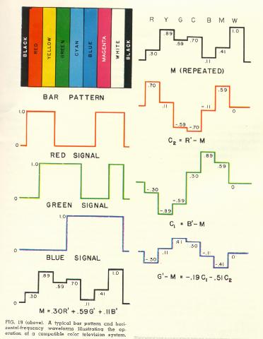
Fig. 20 shows the derivation of the composite signal waveform that would be produced if all three signal components were transmitted at unity level relative to each other. 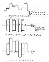 The R-M and B-M signals are modulated upon subcarriers of the same frequency but 90 degrees apart in phase. When the two subcarrier components are added, a resultant corresponding to the vector sum of the two components is produced for each color bar interval. On the scale used in Fig. 20, only the envelope of this subcarrier signal can be shown. When this resultant is in turn added to the M component, the signal shown in the bottom waveform sketch is produced (note that sync and burst waveforms are also shown). A study of this complete waveform quickly shows that it is undesirable to transmit all three components at a relative level of unity, because the addition of the subcarrier signal to the luminance signal causes "overshoots" into the whiter-than-white and blacker-than-black signal regions, greatly increasing the total amplitude range required for the composite signal. A signal of this sort, requiring about 1.84 times as much amplitude range as a normal black-and-white signal, could not be completely compatible with the existing black -and-white broadcast service, because the only way this signal could be through existing broadcast transmitters, (and certain pieces of studio equipment) would be by reducing its absolute amplitude, and reducing the effective modulation of the picture carrier.
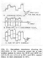 The solution to the relative-amplitude problem used in the FCC Signal Specifications is shown in Fig. 21. The M component is transmitted at the same relative level as an ordinary black-and-white signal, so that no adjustment need be made of receiver contrast controls when a switch is made from a black-and-white to a color program. The amplitude of the R-M and B-M components are reduced to 87.7% and 49.3% respectively, however, so that maximum subcarrier overshoots in the composite signal never exceed 33% of the black-to-white range. It has been found through field test experience that overshoots of this magnitude can be handled in a practical system without impairing performance. Highly saturated colors producing whiter-than-white subcarrier overshoots that cannot be passed without distortion through television transmitters are almost never encountered in actual television scenes. It would be undesirable to reduce the subcarrier amplitudes enough to eliminate all overshoots, because then the signal-to-noise performance of the chrominance channels would be rather poor.
One great advantage of a simultaneous color television system (in which all three signal components are transmitted continuously) as opposed to a sequential system (in which a single transmission path is time-shared by the three components) is that the total available bandwidth may be allotted to the signal components in proportion to the amount of information required by the eye from those signal components. The amount of information (i.e., the amount of pictorial detail) that may be transmitted by the M or luminance component of a compatible color television signal is essentially the same as for a standard black-and-white system, and hence the resolution capabilities of the two systems are about the same. The amount of chrominance information that may be transmitted depends, in large measure, upon the choice of subcarrier frequency. It should be noted here, however, that the requirements for chrominance information are much less than for luminance information. Classic experiments by Bedford of RCA Laboratories and by other research workers have shown that the eye's acuity for differences in hue and saturation is only about 20 to 50% of the acuity for brightness differences.
There are two reasons why it is desirable to make the subcarrier frequency in a compatible color television system as high as possible: (1) Most mass-produced receivers have video response curves which fall off rather rapidly for the higher video frequencies, so a high subcarrier frequency would be attenuated more (and hence be less likely to cause spurious effects in black-and-white pictures) than a lower frequency. (2) The dots produced by imperfect cancellation of the subcarrier are finer in texture, and hence less visible, the higher the subcarrier frequency. On the other hand, a relatively low subcarrier frequency permits a wider upper sideband for the subcarrier signal, and thus increases the bandwidth available for transmitting two independent chrominance components.
In order to utilize the frequency-interlace principle to best advantage, the precise subcarrier frequency should be harmonically related to one-half the line frequency by some odd number which can be factored into smaller numbers that can be handled in practical counting circuits. The precise subcarrier frequency selected as the best compromise among all the factors involved is 3.579545 megacycles, which is 455/2 times the line frequency when the latter is defined as 2/572 times 4.5 MC, which is the standard spacing between the picture and sound carriers in the standard broadcast channel. The line frequency as defined above is 0.1% lower than the nominal 15.75 KC value used in the existing broadcast standards. but is well within the current tolerance limits. The picture to-sound carrier spacing, the line frequency, and the subcarrier frequency are related in this way in the FCC Signal Specifications in order to minimize the visibility of any spurious beat between the subcarrier and the sound carrier; since the frequency separation between the subcarrier and sound carrier is an odd multiple of one-half the line frequency, the beat tends to cancel through frequency interlace.
In practical operation, an oscillator operating at 3.579545 MC serves as the frequency standard for the color television system. A 455-to-one counter (operating in stages of 5, 7, and 13) in combination with a times-4 multiplier provides a 31.5 KC (nominal) signal for the control of a standard synchronizing generator. Within the sync generator, the 31.5 KC is used directly to control the equalizing pulses and the slots in vertical sync, while a divide by-2 counter provides 15.75 KC (nominal) for horizontal sync and blanking, and a 525-to-1 counter (operating in stages of 5, 5, 7, and 3) provides 60 cycles (nominal) for the control of vertical sync and blanking.
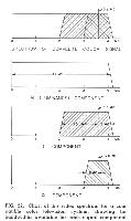 Fig. 22 is a sketch of the video spectrum available for a compatible color television system employing a subcarrier frequency of approximately 3.6 MC. Note that double sidebands can be obtained only for components within about .5 MC of the subcarrier. Since the two-phase modulation process requires double sidebands for crosstalk-free operation, we cannot transmit two independent signals on the subcarrier with bandwidths greater than about .5 MC. A considerably wider lower sideband is available, however, and it is quite feasible to transmit one subcarrier component in this single-sideband region. As shown by the lower sketches in Fig. 22, it appears that by using two-phase modulation and frequency interlace, we have spectrum space for three independent signals within a standard television channel. One of these, which should be used for the M or luminance signal, has a bandwidth of approximately 4.1 MC. One subcarrier component, which we may call the I (or in-phase) component, may have a bandwidth of 1.5 MC if transmitted in semi-single sideband fashion (practical filter limitations make it difficult to achieve effective bandwidths much greater than half the subcarrier frequency). The other subcarrier component, which we may call the Q (or quadrature phase) component, may have a bandwidth of .5 MC with double sidebands.
Let us now consider how we may best fit the chrominance signals into the available channels. It would be possible, of course, to transmit one of the two chrominance signals we have already discussed -say, R-M-by way of the I channel, and to transmit the other (B-M) by way of the Q channel, but this would not produce optimum results. Recent studies of human vision have shown that the acuity of the normal eye for hue and saturation differences, while always much lower than for brightness differences, is not the same for all color combinations. It seems reasonable, therefore, to make the wide-band chrominance signal in a compatible color television system correspond to those color differences for which the eye has greatest acuity.
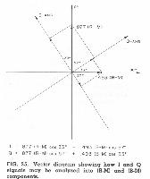
A useful diagram for studying this problem is the vector diagram formed by combining the subcarrier vectors for all the colors shown in Fig. 19. Such a diagram is shown in Fig. 23, with relative amplitudes and phases corresponding to those shown in Fig. 21. 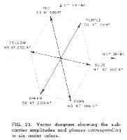 This diagram is roughly comparable to the color circle used by primary school children. The phase angle gives a good indication of hue, while the subcarrier amplitude, when considered along with the corresponding luminance level, gives an indication of saturation. White or neutral colors fall at the center of the diagram, since these produce no subcarrier component. Any given chrominance or color difference signal corresponds to an axis or line on this vector diagram. For example, R-M and B-M correspond to the pair of lines indicated as the coordinate axes for Fig. 23.
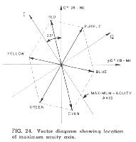 Extensive experiments at the RCA I,aboratories indicated that the eye has greatest acuity for color differences corresponding to an axis displaced from the R-M axis by 33', as shown in Fig. 24. This axis corresponds to colors ranging from orange to cyan (or blue-green). It seems reasonable, therefore, to arrange the compatible color system so that I, or wide-band, component corresponds to this orange-cyan axis, while the Q component corresponds to the axis at right angles to this, along which the eve has relatively little acuity. The specifications for the I and Q signals may be determined by projecting the R-M and B-M signals (at the previously-determined levels) into the I and Q phase directions. This operation is illustrated graphically in Fig. 25. The same signal produced by adding .877(R-M) and .493(B-M) in phase quadrature can also be produced by adding I and Q in phase quadrature when
The expression for M in terms of R, G, and B may be substituted into the above equations to show I and Q as functions of red, green, and blue, as follows:
These equations show how I and Q signals may be produced directly from the camera signals at the transmitting end of the system without going through an intermediate R-M, B-M stage. It is also possible to solve the first set of equations above to show how R-M and B-M may be obtained by cross mixing the outputs of I and Q demodulators in a color receiver. The desired expessions are:
The G-M signal needed to combine with the M signal to control the green primary in a receiver may be obtained either by cross-mixing (R-M) and (B-M) signals, as shown in Fig. 8, or by cross-mixing I and Q signals directly, as indicated by the following equation:
In the preceding pages, we have discussed most of the major principles and techniques employed in the RCA color television system. It would be well at this point to look at the system as a whole to see how the various principles are interrelated. This review will also give us an opportunity to examine briefly some details of the system not covered in earlier discussions.
All major operations performed at the transmitting end of the system are shown in Fig. 26. The camera contains three pickup tubes or transducing elements which provide electrical signals corresponding to the red, green, and blue components of the scene to be televised. These signals are passed through non-linear amplifier stages (the gamma correctors) which provide compensation for the non-linearity of the kinescope elements at the receiving end of the system. The gamma-corrected signals are then matrixed or cross-mixed to duce a luminance signal (M) and two color-difference or chrominance signals (I and Q). Fig. 26 shows a simple matrix circuit for producing M, I, and Q signals directly from the R, G, B signals in accordance with the equations previously given.
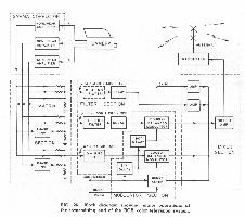 In the "filter section" shown in Fig. 26, the bandwidths of the M, I, and Q signals are established. The 4.1 MC filter for the luminance channels is shown in dotted lines because in practice it is not necessary to insert a special filter to achieve this band-shaping-the bandwidth of the luminance signal is usually determined by the attenuation characteristics of the transmitter, which must, of course, confine its radiation to the assigned broadcast channel. The bandwidths of 1.5 MC and .5 MC shown for the I and Q channels, respectively, are nominal only - the required frequency response characteristics are described in more detail in the complete FCC Signal Specifications. Delay compensation is needed in the filter section in order to permit all signal components to be transmitted in time coincidence. In general, the delay time for relatively simple filter circuits varies inversely with the bandwidth-the narrower the bandwidth, the greater the delay. Consequently, a delay network or a length of delay cable must be inserted in the I channel to provide the same delay introduced by the narrower-band filter in the Q channel, and still more delay must be inserted in the M channel.
In the modulator section, the I and Q signals are modulated upon two subcarriers of the same frequency but 90 degrees apart in phase. The modulators employed should be of the doubly-balanced type, so that both the carriers and the original I and Q Signals are suppressed, leaving only the sidebands. Some sort of keying circuit must be provided to produce the color synchronizing bursts during the horizontal blanking intervals. To comply with the FCC Signal Specifications, the phase of the burst should be 57 degrees ahead of the I component (which leads the Q component by 90 degrees). This phase position, which places the burst exactly 180 degrees out of phase with the B-M component of the signal, was chosen mainly because it permits certain simplifications in receiver designs. Timing information for "keying in" the burst may be obtained from a "burst flag generator", which is a simple arrangement of multivibrators controlled by horizontal and vertical drive pulses.
In the mixer section, the M signal, the two subcarriers modulated by the I and Q chrominance signals, and the color synchronizing bursts are all added together. Provision is also made for the addition of standard synchronizing pulses, so that the output of the mixer section is a complete color television signal containing both picture and synchronizing information. This signal may then be put "on the air" by means of a standard television transmitter, which must be modified only to the extent necessary to assure performance within the reduced tolerance limits required by the color signal. (Since the color signal places more information in the channel than a black-and-white signal, the requirements for frequency response, amplitude linearity, and uniformity of delay time are more strict).
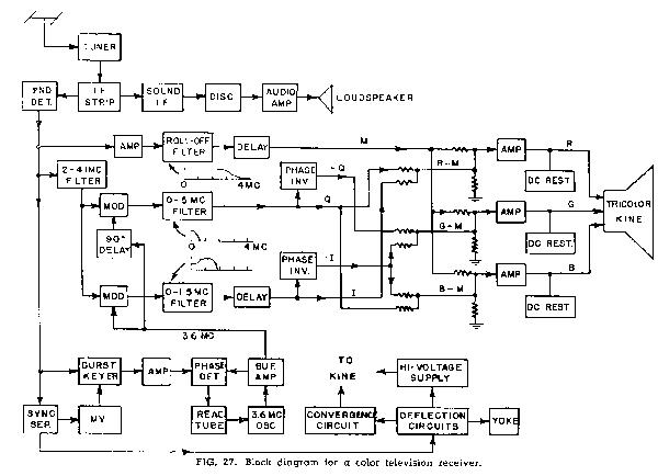
The basic operations performed in a compatible color receiver are shown in Fig. 27. The antenna, RF tuner, IF strip, and second detector serve the same functions as the corresponding components of a black-and-white receiver. The sound signal may be obtained from a separate IF amplifier, or it may be obtained from the output of the second detector by using the well known "intercarrier sound" principle. The video signal obtained from the second detector of the receiver is, for all practical purposes, the same signal that left the color studio. The receiver up to this point is no different from a black-white receiver except that the tolerance limits on performance are somewhat tighter.
The signal from the second detector is utilized in four circuit branches. One circuit branch directs the complete signal toward the color kinescope, where it is used to control luminance by being applied to all kinescope guns in equal proportions. In the second circuit branch, a band-pass filter separates the high-frequency components of the signal (roughly 2.0 to 4.1 MC) consisting mainly of the two-phase modulated subcarrier signal. This signal is applied to a pair of modulators which operate as synchronous detectors to recover the original I and Q signals. It should be noted that those frequency components of the luminance signal falling between about 2 and 4.1 MC are also applied to the modulators, and are heterodyned down to lower frequencies. These frequency components do not cause objectionable interference, however, because they are frequency-interlaced and tend to cancel out through the persistence of vision.
The remaining two circuit branches at the output of the second detector make use of the timing or synchronizing information in the signal. A conventional sync separator is used to produce the pulses needed to control the horizontal and vertical deflection circuits which are also conventional. The high voltage supply for the kinescope may be obtained either from a "fly back" supply associated with the horizontal deflection circuit or from an independent RF power supply. Many color kinescopes require convergence signals to enable the scanning beams to coincide at the screen in all parts of the picture area; the waveforms required for this purpose are readily derived from the deflection circuits.
The final branch at the output of the second detector is the burst gate, which is turned "ON" only for a brief interval following each horizontal sync pulse by means of a pulse obtained from a multivibrator, which is in turn controlled by horizontal sync pulses. The separated bursts are amplified and compared with the output of a local oscillator in a phase detector. If there is a phase difference between the local signal and the bursts, an error voltage is developed by the phase detector. This error voltage restores the oscillator to the correct phase by means of a reactance tube connected in parallel with the oscillator's tuned circuit. This automatic-frequency control circuit keeps the receiver oscillator in synchronism with the master subcarrier oscillator at the transmitter. The output of the oscillator provides the reference carriers for the two synchronous detectors; a 90 degree phase shifter is necessary to delay the phase of the Q modulator by 90 degree relative to the I modulator.
There is a "filter section" in a color receiver that is rather similar to the filter section of the transmitting equipment. The M, I, and Q signals must all be passed through filters in order to separate the desired signals from other frequency components which, if unimpeded, might cause spurious effects. The I and Q signals are passed through filters of nominally 1.5 and .5 MC bandwidth, respectively, just as at the transmitting end. A step-type characteristic is required for the I filter, as indicated by the sketch in Fig. 27, to compensate for the loss of one sideband for all frequency components above about .5 MC. A roll-off filter is desirable in the M channel to attenuate the subcarrier signal before it reaches the kinescope. The subcarrier would tend to dilute the colors on the screen if it were permitted to appear on the kinescope grids at full amplitude. Delay networks are needed to compensate for the different inherent delays of the three filters, as explained previously.
Following the filter section in the receiver there is a matrix section in which the M, I, and Q signals are cross-mixed to recreate the original R, G, B signals. The R, G, B signals at the receiver are not identical to those at the transmitter because the higher frequency components are mixed, and are common to all three channels. This mixing is justifiable, because the eye cannot perceive the fine detail (conveyed by the high-frequency components) in color. There are many possible types of matrixing circuits; resistance mixers shown in Fig. 27 provide one simple and reliable approach. For ease of analysis, the matrix operations at the receiver may be considered in two stages. The I and Q signals are first cross-mixed to produce R-M, G-M. and BM signals (note that negative I and Q signals are required in some cases), which are, in turn, added to M to produce R, G, and B.
In the output section of the receiver, the signals are amplified to the level necessary to drive the kinescope, and the DC component is restored. The image which appears on the color kinescope screen is a high-quality, full-color image of the scene before the color camera.
The writer hopes that this brief description of the RCA color television system has helped the reader to understand the major technical features of the system. We are, even now, on the threshold of an era in which color television is sure to find place as an important broadcast service the American public. The RCA system not only provides excellent performance in it present state of development, but also has great potentialities for future improvement. As the basic principles of compatible color television become more thoroughly understood by engineers throughout the industry, we may expect the rapid development of- improved kinescopes, cameras, studio equipment, and low-cost receivers. The day is not far distant when color television programs will be as commonplace as the black-and-white programs of today.
Footnotes
/1 Brightness, strictly speaking, is a psychological sensation not susceptible to exact measurement. Luminance, which we can measure by taking into account the intensity of the radiation from the color in question and also the spectral response of the typical eye, indicates only the strength of the stimulus that controls the brightness sensation. While luminance can be measured in absolute units (the foot-lambert being the most common) it is generally preferable to use relative units; i.e., the luminances in a television image can best be expressed as percentage of the maximum highlight luminance. The reason for this is that the normal observer tends to perceive as "white" the brightest area in his field of vision, even though the actual intensity of the brightest area may be much lower some circumstances than others.
BACK to NRC articles page