

This new 5-kw AM transmitter, type BTA-5T, incorporates the only worthwhile development in class "C" power amplifier design in 20 years. The newly-designed PA circuit operates with a plate efficiency of 90 percent. This represents an improvement of 20 percent over normal class "C" operation. As a direct result power savings of approximately 15,000 kilowatt hours per year can be realized.
Basically, the new transmitter uses the design proved in the BTA-5R/5R1. (see footnote 1).
However, using the recently-developed high-efficiency circuit, only one PA tube is needed. Other circuit innovations (such as silicon rectifiers and improved protection) have been made to improve performance and to extend operating life.
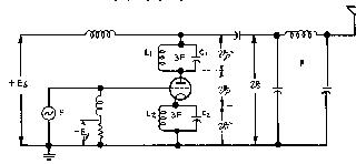
The high-efficiency plate-modulated power amplifier uses a single tube to deliver the nominal 5 kw with 5.5 kw power output capability at 90 to 92 percent plate power conversion. Referring to the simplified schematic, the circuit arrangement is very similar to a conventional class "C" amplifier except for presence of two resonators L1, C1, and L2, C2. In fact, the new high-efficiency stage behaves so much like the conventional class "C" stage that with, the resonator shorted, or mis-tuned, the PA tube returns from the high-efficiency to the conventional class "C" operation. This characteristic, as will be shown later, is very useful in the initial tune-up of the transmitter. For the moment it will be helpful in making a detailed comparison.
In both systems the angle of the tube current conduction is restricted to that portion of the cycle wherein the instantaneous plate current is high and the instantaneous plate voltage low, corresponding to a low anode dissipation at a relatively high-power output. In the class "C" operation, however, the waveform is sinusoidal and is substantially rounded off. Therefore, a large portion of the power is lost in the anode, resulting in an average efficiency of about 70 percent. The new system provides corrective means for maintaining a flat waveform near the peak, resulting in 90 percent average plate efficiency.
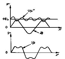
The waveshaping is done by two LC parallel resonant circuits, one located in the plate and the other in the cathode circuit of the power amplifier tube. Both resonators are adjusted to resonate at the third harmonic of the carrier frequency.
When the amplifier tube is driven, the harmonic component of the grid input power sets up and maintains circulating current within each resonator. Since the resonator is designed to store high KVA, the total voltage supply at the plate is composed of the usual d-c plate supply and the superimposed oscillatory potential equal to the voltage build-up across the resonator. This oscillatory voltage, being at the third harmonic, vectorially adds twice to, and subtracts once from the fundamental, producing a flat top waveform (see 7A). When the cathode resonator is adjusted to resonate at the third harmonic, the instantaneous grid-to-cathode potential modifies the cathode emission to approximate a rectangular pulse (see Fig. 7B).
In the BTA-5T transmitter, adjustment of the plate resonator improves the efficiency by 6 to 8 percent. Subsequent adjustment of the cathode resonator improves the efficiency by an average total of 20 percent above conventional class "C" operation.
The energy stored within the resonator modifies the instantaneous current voltage waveform of the conventional class "C" amplifier to reduce its amplitude and broaden the top. For the same power output this means not only reduction in the plate dissipation, but also considerable reduction in peak-plate to plate-peak grid current and operation at a much lower cathode emission (see Table I). As the result of the high-efficiency operation, the BTA5T transmitter employs only one PA tube, an RCA type 5762. It is worthy to note that plate dissipation in the new system is comparable to the filament power consumption of the old.
| BTA-5R | BTA-5T | ||
| Output Amplifier (Carrier) Output Power | kw | 5.0 | 5.0 |
| Number of tubes (RCA 5762) | 2 | 1 | |
| Inst. Plate Current (calculated) * | Amps | 5.6 | 3.5 |
| Inst. Grid Current | Amps | 2.7 | 1.8 |
| Peak Cathode Emission | Amps | 8.3 | 5.3 |
| Plate Dissipation | kw | 1.5 | .57 |
| Filament Power | kw | .74 | .37 |
| Plate Efficiency | % | 76 | 90 |
| Modulator & Power Ampl (100% Mod) | kw | 2.25 | .85 |
| Modulator Plate Dissipation | kw | 2.0 | 1.7 |
| Overall Input | kw | 13.3 | 11.2 |
| Overall Efficiency | % | 56.4 | 67 |
| Transmitter Power Input (.95 P.F.) Carrier | kw | 11.6 | 10.0 |
| Average Program | kw | 12.7 | 11.0 |
| Input Power/Yr Saving | kwh | - | 15,000 |
The third important feature in favor of the new transmitter is: simplicity of the initial tune-up and stability of operation. Upon mistuning the harmonic resonator, the PA tube returns from the high-efficiency to the conventional class "C" operation. Except for the loss in the efficiency of the PA, the circuit neutralization, tank tuning, the stage loading remains the same for both type of operation.
Applying the above procedure in reverse, the initial tune-up consists of the resonator adjustment to obtain the maximum power output as indicated by the line or the antenna current ammeter. The plate resonator chiefly contributes toward the power output, while the cathode resonator in addition to increasing power output to some extent increases the power input.
With the system properly in operation, tuning of the output tank is similar to tuning of the conventional class "C" amplifier, except the tuning is broader. On either side of the tuning-dip the plate current rise is more gradual, the power output slightly rising on one side and falling on the other side. This self-adjusting property would provide additional stability in the case of accidental mistuning or mistuning due to a reactive load.
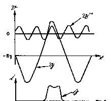
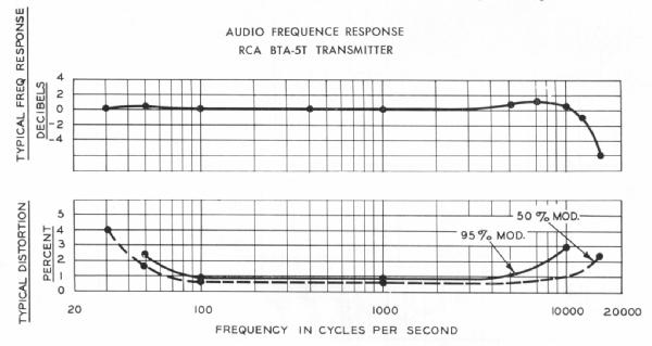
Both the conventional and the high efficiency system were compared using essentially the same transmitter circuit with identical components. Each offered similar performance insofar as modulation capability, audio distortion, carrier shift and noise level are concerned (see Fig. 8). Tests were carried out over the broadcast frequency range, using a number of tubes of different socket life. Therefore, the high-efficiency class "C" operation data listed in Table I may be considered as typical for this power level and frequency of operation.2
In order to determine what effects the high efficiency circuit would have upon 5762 tube life, tubes with known expectancy life characteristics were obtained and placed for service in a transmitter operating at maximum conditions with greater than average modulation applied for extended periods of time. The tubes were then retested, opened, the parts measured, and examined for evidence of deterioration. It was found that the life expectancy of all the tubes examined to be as good or greater than the expected life of tubes operating under conventional class "C" service.
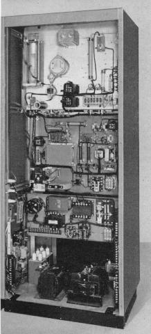
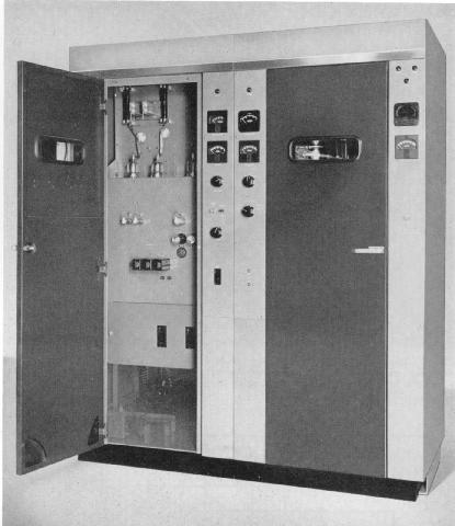
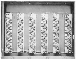
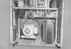
The entire transmitter, except the plate transformer, is housed in two attractively styled cabinets (see Fig. 1). All meters, indicators, control switches and tuning controls are located on the front panels. Vertical center chassis are fastened between the end panels to form a basic "H" cross section. The front doors give immediate access to tubes, feedback ladders and overload relays, which are mounted on the vertical chassis (see Fig. 2). Remaining components are mounted on the rear of these chassis, behind removable rear panels, while the large power components are mounted on the base of the cabinet. This type of construction offers excellent accessibility, while retaining the compactness of the transmitter (see Fig. 9).
A simplified schematic of the BTA-ST transmitter is shown in Fig. 6. The exciter unit, the PA modulator driver stages and the high-level linear modulator remain essentially the same as in BTA-5R/5RI transmitter. The power supplies are silicon rectifier type. New instantaneous circuit breakers are employed in the control circuits. The plate-modulated power amplifier is of course improved by virtue of the new high-efficiency technique and the resultant power and tube savings.
The BTA-5T transmitter has only two front panel tuning controls with one local-remote power control. The driver stage is tuned by means of a slug-tuned coil, and the PA by means of a variable vacuum capacitor. Remaining circuit adjustments, necessary only at installation, consist of tap changing in accordance with the calibration chart. The PA plate resonator is adjusted by means of a front panel screwdriver slot actuating a variable vacuum capacitor. Capacitor of the cathode resonator is adjusted in similar manner. Both capacitors are adjusted for peak of the line ammeter. The variable vacuum PA neutralizing capacitor, employed in conjunction with a broadband neutralizing transformer is also preset at the initial installation.
The BTA-5T uses silicon-type rectifiers throughout. This type of rectifier offers excellent reliability in normal operation and even more so in a remote-control application. The transmitter will operate within ambient temperatures from -20 to +45 degrees and up to 7500 feet above sea level.
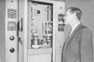
The proven reliability high-voltage rectifier (see Fig. 10) is arc-back protected for trouble free operation, requiring neither warm-up time nor thermostatic cooling control. It carries an over-current safety factor of 200 percent, or in other words, it is capable of continuous short circuit operation. The peak inverse voltage rating is 180 percent, allowing 30 percent above the starting transient and the silicon peak inverse voltage safety factor.
The bias and low-voltage rectifiers are sealed silicon units permitting a more reliable operation.
To increase reliability, improvements were made in the control and protective circuitry of the BTA-5T transmitter. Primary lines are protected by circuit breakers with instantaneous and thermal overload trip protection. The 3-phase blower motor is protected by a contactor with thermal cutoff in each phase; the relay switching is sequential so that the filament not come on unless the blower is operating. Starting surges in the plate transformer, high-voltage reactor, and the filter capacitor are eliminated by the use of step-start and damping circuit.
In keeping with modern trends, the transmitter is air cooled. Added refinements such as a delay relay have been built-in, to keep the blower system in operation for one minute after the transmitter has been shut down. This continues the supply of air to extend tube life. As the result of the high efficiency, the air pressure has been reduced, permitting use of a slow speed blower unit, resulting in quiet operation. (see Fig. 11).
Many years of design experience are reflected throughout. Functional styling predominates affording convenience of operation, furthermore, the user has a choice of red, or gray doors to enhance the station decor.
Emphasis, however, has been placed on the reliability and the dependable performance of the transmitter. This will result in many years of trouble-free operation. Power savings achieved by the new high-efficiency circuits provide for economical operation without sacrifice of performance.
BACK to NRC articles page